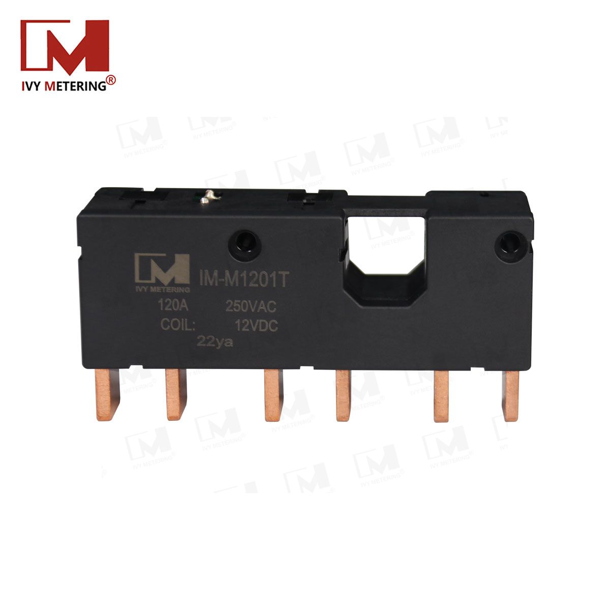
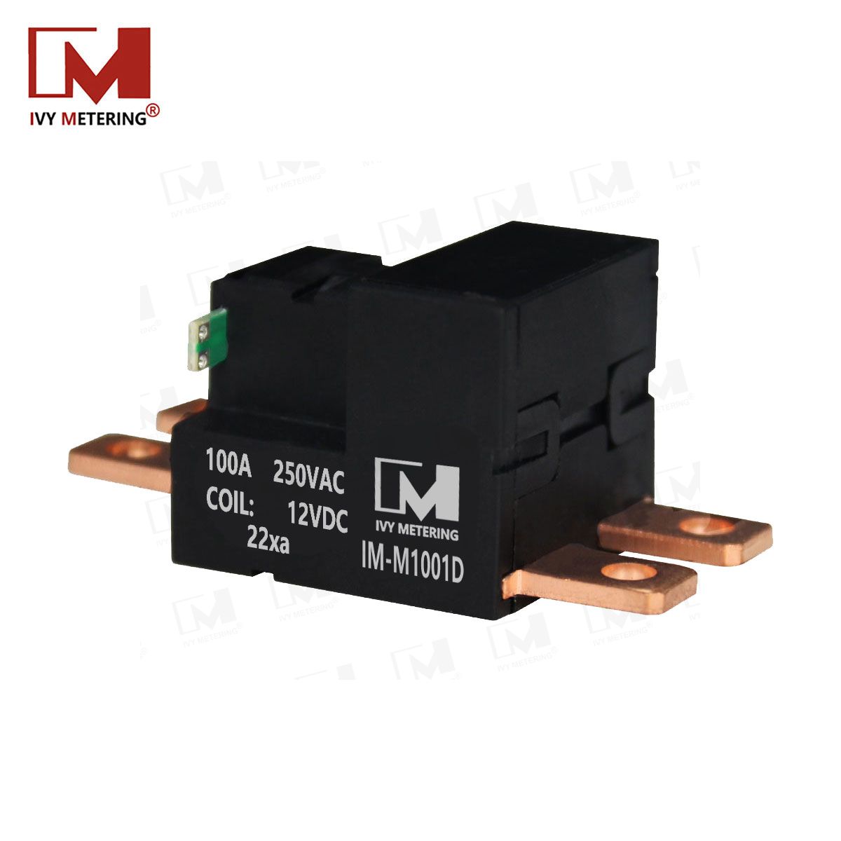
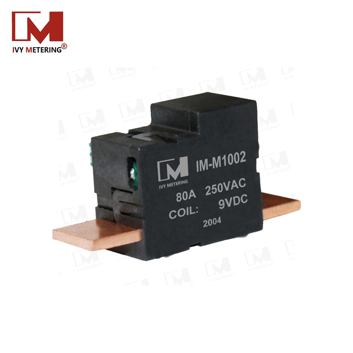
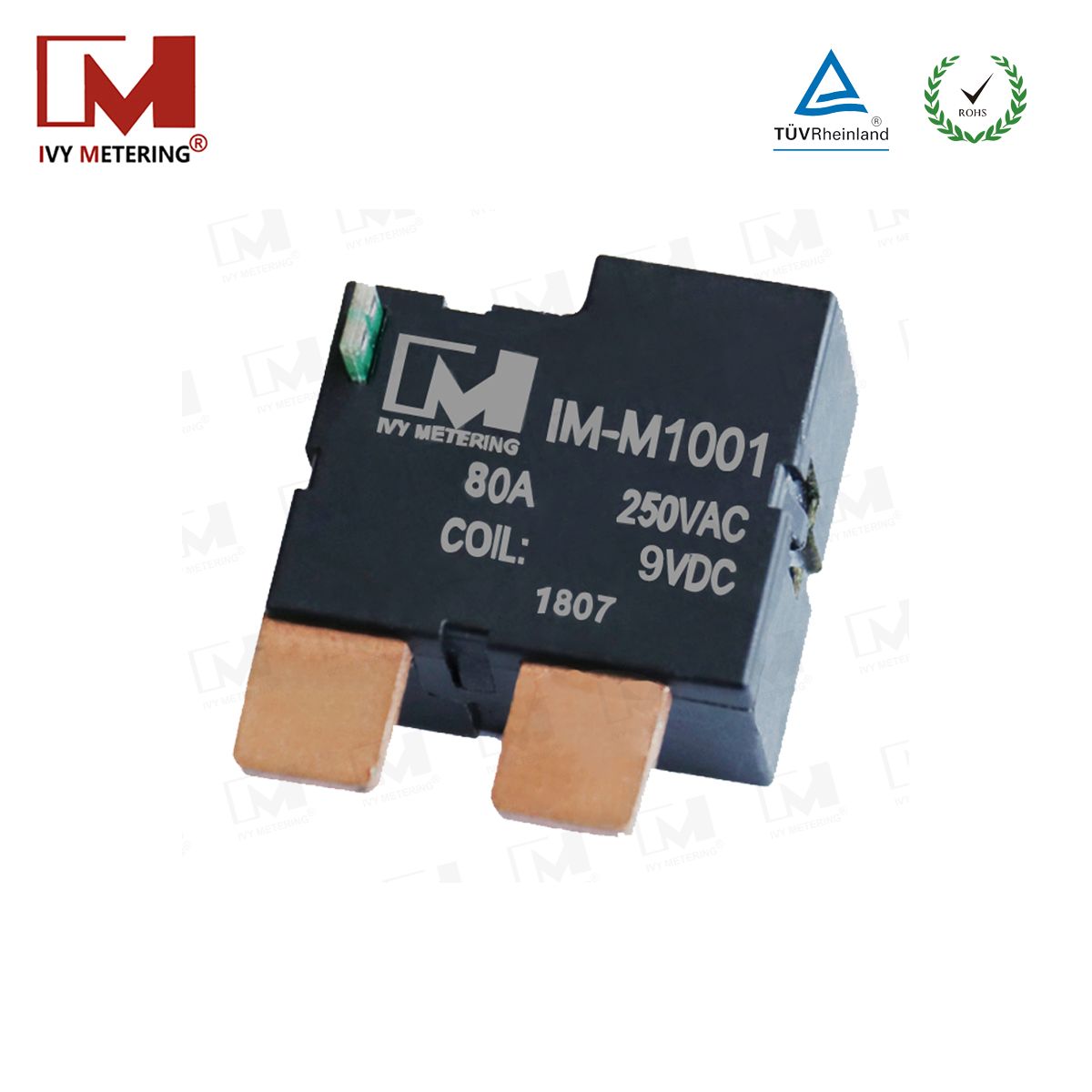
IM-M1202 100A Magnetic Latching Relay for Smart Meters and Power Control
High-current switching: Maximum switching current of 100A.
Magnetic immunity: Designed to resist permanent magnetic fields up to 500mT under specified test conditions.
Compact dimensions: Approximately 29 × 23.5 × 16 mm.
Low switching energy: Published power consumption below 3W during the specified operating pulse.
Bistable operation: Maintains its switching state without continuous motor energization.
Low contact resistance: Maximum specified contact resistance of 1.0mΩ.
High surge capability: Published surge immunity of 6000A for 10ms.
Wide temperature range: Operating ambient temperature from -40°C to +75°C.
Long mechanical life: More than 100,000 mechanical operating cycles under specified test conditions.
OEM/ODM support: Contact IVY Metering to discuss application requirements and available configurations.
Key Features of the IM-M1202 Latching Relay
High-current switching: Maximum switching current of 100A.
Magnetic immunity: Designed to resist permanent magnetic fields up to 500mT under specified test conditions.
Compact dimensions: Approximately 29 × 23.5 × 16 mm.
Low switching energy: Published power consumption below 3W during the specified operating pulse.
Bistable operation: Maintains its switching state without continuous motor energization.
Low contact resistance: Maximum specified contact resistance of 1.0mΩ.
High surge capability: Published surge immunity of 6000A for 10ms.
Wide temperature range: Operating ambient temperature from -40°C to +75°C.
Long mechanical life: More than 100,000 mechanical operating cycles under specified test conditions.
OEM/ODM support: Contact IVY Metering to discuss application requirements and available configurations.
Product Parameters
Basic Data | Dimension (mm) | 29*23.5*16 | |
Weight | ≈40g | ||
Contact Form | 1A/1B | ||
Contact Material | AgSnO2 | ||
Ambient Temperature | -40~+75℃ | ||
Vibration | 1.0mm(DA),10 to 55Hz | ||
Shock | 1000m/s²,(100G) | ||
Power Consumption | <3W | ||
Operating Voltage | 10.5-16V | ||
Max. Switching Current | 100A | ||
Surge Immunity | 6000A/10ms | ||
Motor Resistance | 32(1±15%)Ω | ||
Contact Voltage | <60mV | ||
Contact Resistance | ≦1.0mΩ | ||
Dielectric Strength | Micro-motor to contact | >4000VAC,50/60Hz,1 Min | |
Across open contact | >2000VAC,50/60Hz,1 Min | ||
Electrical Endurance(120 cycles/H) | >10,000 Cycles · (resistance 5 k + perceptual 5 k, co ϕ = 0.5) | ||
Mechanical Endurance(3600 cycles/H) | >100,000 Cycles | ||
Pulse Time | ≥60ms(Advise 60ms~100ms) | ||
Pick-up Time | ≤60ms | ||
Release Time | ≤60ms | ||
Insulation Resistance | >1000MΩ(500VDC) | ||
Product Dimension

Applications of the IM-M1202 100A Latching Relay
1. Smart Electricity Meters
The IM-M1202 can be evaluated for controlled load switching in smart electricity meters. Its compact dimensions and magnetic immunity make it a candidate for metering designs where space constraints and resistance to external magnetic interference are important.
2. Prepaid and Postpaid Energy Metering
In prepaid and postpaid electricity metering systems, a latching relay can support remote load connection and disconnection functions. The final design must account for the meter's rated current, load characteristics, switching duty, and applicable metering standards.
3. Power Distribution Units
The IM-M1202 may be considered for compact power distribution equipment requiring high-current switching and a bistable relay mechanism. Verify its suitability for the intended AC or DC load and the required isolation and safety standards.
4. Energy Management Systems
Energy management equipment can use latching relays for controlled power switching while minimizing continuous coil energization. The IM-M1202's compact size may help equipment manufacturers optimize internal layout.
5. Industrial Power Control
The IM-M1202 can be evaluated for industrial control applications that require high-current switching, resistance to external magnetic interference, and compact integration.
Why Choose a 500mT Magnetic Immunity Latching Relay?
External magnetic fields can affect the operation of certain electromechanical devices. In applications such as smart electricity meters, magnetic immunity can be an important consideration for operational reliability and resistance to magnetic interference.
The IM-M1202 is specified for permanent magnetic immunity up to 500mT under defined test conditions. This feature makes it worth evaluating for equipment installed in environments where external magnetic interference is a design consideration.
Magnetic immunity should be assessed together with contact ratings, insulation performance, operating temperature, mechanical endurance, and applicable product certification requirements.
IM-M1202 vs. Conventional Non-Latching Relays
| Comparison Item | IM-M1202 Magnetic Latching Relay | Conventional Non-Latching Relay |
|---|---|---|
| Operating Principle | Motorized bistable latching | Typically monostable |
| State Retention | Maintains the last switching state without continuous motor energization | Typically requires continuous coil energization to maintain the energized state |
| Holding Power | No continuous motor power is required to retain the latched state | Typically consumes coil power while energized |
| Magnetic Immunity | Specified at 500mT under defined conditions | Depends on the particular relay design |
| Switching Current | Maximum published switching current of 100A | Varies by model |
| Installation Space | Compact 29 × 23.5 × 16 mm body | Varies by model |
| Selection Considerations | Load ratings, drive pulse, magnetic immunity, contact configuration, and certification | Coil rating, load capacity, switching duty, and environmental conditions |
The most suitable relay depends on the electrical load, switching frequency, control circuit, installation dimensions, and safety requirements. Compare the complete specifications rather than selecting by current rating alone.
Frequently Asked Questions
What is the maximum switching current of the IM-M1202?
The published maximum switching current of the IM-M1202 is 100A. The permissible operating current must be confirmed against the applicable load type, voltage, switching conditions, and approved product ratings.
What does 500mT magnetic immunity mean?
The 500mT specification describes the relay's stated resistance to a permanent magnetic field under defined test conditions. Customers should request the relevant test method and certification documents when evaluating the relay for applications with specific magnetic immunity requirements.
Does the IM-M1202 consume power continuously?
The IM-M1202 uses a motorized latching mechanism. Once the relay has reached its latched state, continuous motor energization is not required to maintain that state. The published specifications list power consumption below 3W and a pulse duration of at least 60ms, with 60–100ms recommended.
What is the size of the IM-M1202 relay?
The published dimensions are approximately 29 × 23.5 × 16 mm, with a weight of approximately 40g. Confirm the mechanical drawing, terminal layout, and mounting requirements before finalizing the PCB or enclosure design.
Is the IM-M1202 suitable for smart electricity meters?
The IM-M1202 is designed for applications including smart metering and power control. Engineers should verify the rated current, load type, contact configuration, magnetic immunity test conditions, and applicable certification requirements before integration.
Does the IM-M1202 comply with IEC 62055-31 UC3?
The product page references IEC 62055-31 UC3. Request the current certificate or test report to confirm the exact model, applicable standard edition, and scope of compliance before using this claim in a regulated product design.
What information should I provide when requesting a quotation?
Please provide your application, required switching current, load voltage and type, contact configuration, operating environment, magnetic immunity requirements, expected switching frequency, annual quantity, and certification requirements. This information helps IVY Metering evaluate the appropriate relay solution.
Request an IM-M1202 Datasheet or Quotation
Looking for a compact 100A latching relay for smart meters, energy management systems, or high-current power control?
Contact IVY Metering to request the latest IM-M1202 datasheet, confirm electrical and magnetic immunity specifications, review certification documentation, and discuss your application requirements.
Contact IVY Metering for technical support and a quotation.